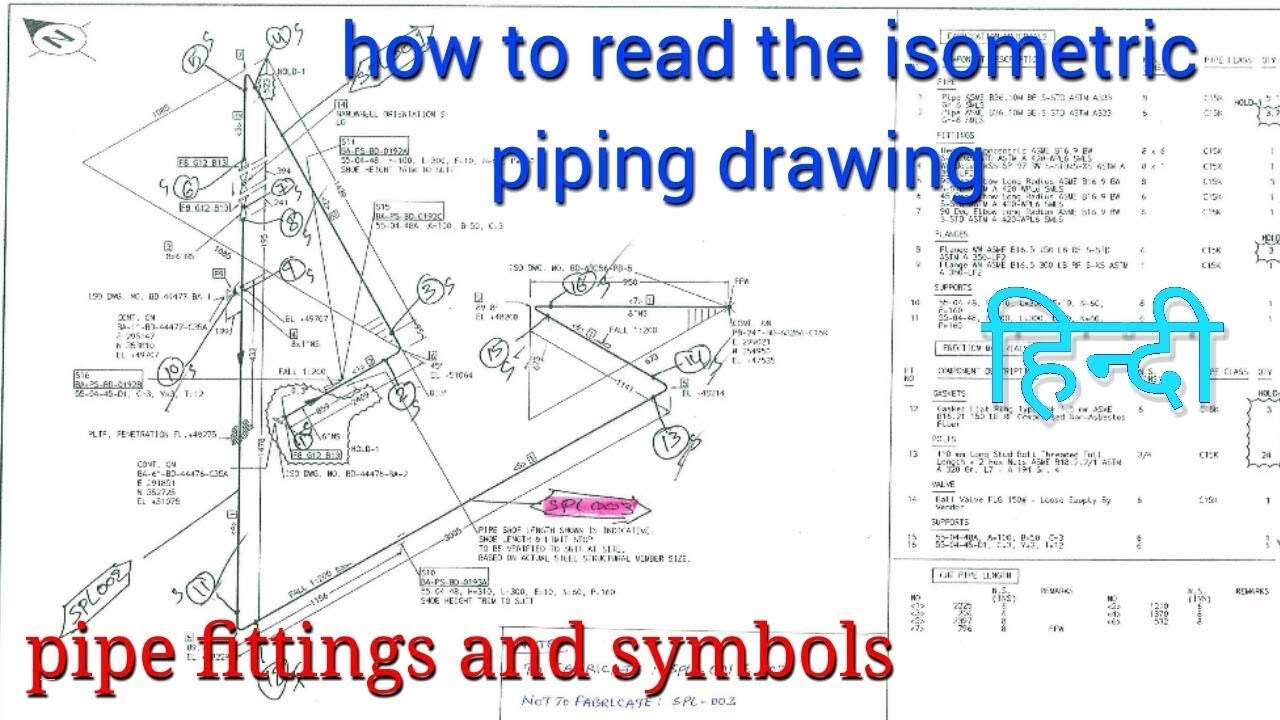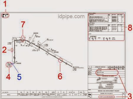


Isometrics drawing is also the most important drawings for installation contractors during the field portion of the project. It is often used by designers prior to a stress analysis and used by draftsmen to produce shop fabrication spool drawings. Piping isometrics are generally produced from orthographic drawings and essential to design and manufacturing phase of a very complex or large piping systems. Vertical pipe lengths are calculated using elevations, while horizontal lengths are calculated using north-south and east-west coordinates. Pipe lengths are measured using coordinates and elevations. Therefore, dimensions are required to specify exact lengths of piping runs. The isometric drawing is oriented on the grid relative to the north arrow found on plan drawings and not drawn to scale. Piping isometrics are usually drawn on a pre-printed paper, with lines of equilateral triangles form of 60°. Symbols like fittings, Valves and flanges are modified to adapt to the isometric grid. The Isometrics drawing are created from information found on a plan and elevation views. Click here to learn more details about Piping Isometric Drawings.In a piping isometrics drawing, pipe is drawn according to it’s length, width and depth, and often shown in a single view. By the Construction, the team to erect the piping items on the site following proper routing.Īll the above drawings are very important project documents and must be prepared with utmost thought and care to reduce the amount of rework at a later stage.By piping material group for purchasing materials.They are not to scale, single-line diagrams with symbols for pipe components, weld points, and supports.

5) represent the pipe routing with proper dimensions including all piping items and equipment.


 0 kommentar(er)
